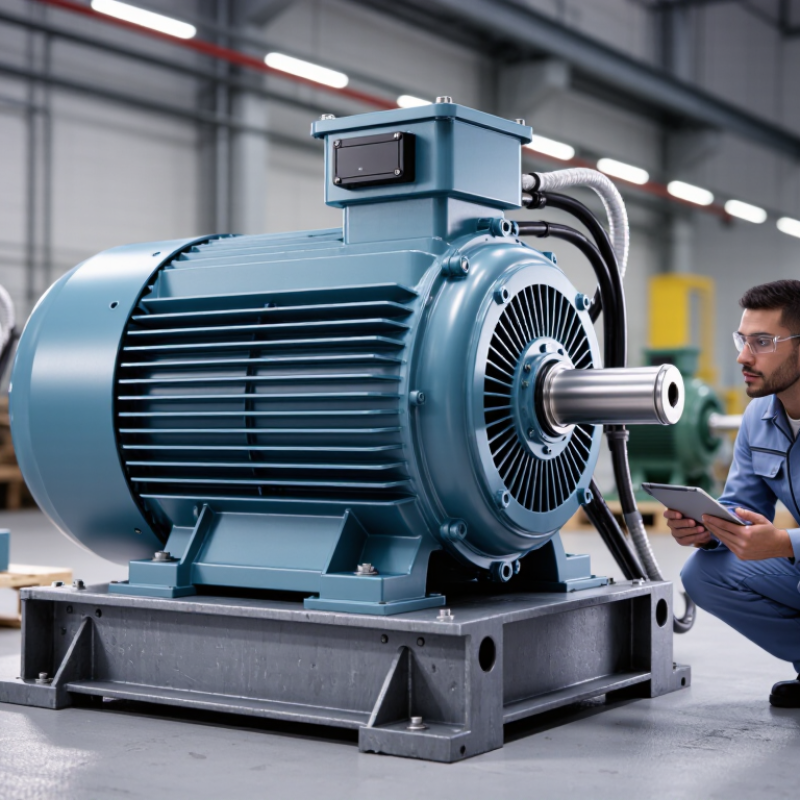
| Cooling System |
IEC 60034-6, IC611
Closed air circuit, air-to-air heat exchanger cooling. |
IC411: Totally enclosed, fan-cooled
IC611: Closed air circuit, air-to-air cooled
IC616: Closed air circuit, air-to-water cooled
|
Select IC611 when the motor must operate in dusty, humid, or contaminated environments and a sealed cooling circuit is preferred. Confirm heat-exchanger capacity at the actual ambient temperature and load.
|
Cooling-code declaration, thermal performance data, airflow or heat-dissipation curves, and temperature-rise test results.
|
| Applicable Standards |
IEC 60034 series
IEC 60034-1 for ratings and performance; IEC 60034-6 for cooling; IEC 60034-5 for enclosure protection. |
IEC-based design
NEMA-based design
Project-specific specifications
|
Use one primary standard system throughout the project. Check rated voltage, frequency, efficiency, temperature rise, vibration, noise, and testing requirements for consistency.
|
Standards list, type-test records, routine-test procedure, nameplate sample, and certificate of conformity where required.
|
| Energy Efficiency |
IE3 minimum for many industrial applications
Consider IE4 for long operating hours or high electricity prices. |
IE2: lower initial cost, higher energy use
IE3: common industrial baseline
IE4: higher efficiency and higher purchase cost
|
For motors operating approximately 4,000–8,000 hours per year, calculate lifecycle cost rather than comparing purchase price alone. Verify efficiency at the rated load and partial-load points.
|
Efficiency test report based on IEC 60034-2-1 or the specified equivalent method, including rated-load efficiency and power factor.
|
| Protection and Environment |
IP55 as a general minimum
Use IP56 or IP66 when water jets, heavy dust, or outdoor exposure are expected. |
IP55: dust-protected and protected against water jets
IP56: dust-protected and protected against powerful water jets
IP66: dust-tight and protected against powerful water jets
|
Select the enclosure rating according to the actual installation conditions. IP rating does not by itself confirm corrosion resistance, chemical compatibility, or suitability for explosive atmospheres.
|
IP test report, enclosure construction details, drain and breather arrangement, paint-system specification, and environmental limitations.
|
| Insulation and Temperature Rise |
Class F insulation with Class B temperature-rise limit
Subject to the motor rating and applicable standard. |
Class F insulation: 155°C insulation-system rating
Class H insulation: 180°C insulation-system rating
Class B rise: lower winding temperature during operation
|
A lower temperature rise generally improves winding life. Confirm suitability for inverter operation, frequent starts, high ambient temperature, and altitude above 1,000 m.
|
Insulation-system data, winding-temperature calculations, surge-protection details for variable-frequency drive use, and altitude derating information.
|
| Duty and Load Profile |
S1 continuous duty
Use the actual load cycle rather than assuming constant full-load operation. |
S1: continuous duty
S2: short-time duty
S3–S8: intermittent or specialized duty cycles
|
For pumps, fans, compressors, and conveyors, specify starting frequency, acceleration time, load inertia, speed range, and minimum operating speed. Oversizing can reduce efficiency and power factor.
|
Duty-cycle calculation, starting-current data, permissible starts per hour, inertia limits, and application-specific performance curves.
|
| Mechanical Reliability |
Bearing L10 life of at least 40,000 hours for direct-coupled applications
Higher targets may be appropriate for continuous-process equipment. |
Standard rolling bearings
Insulated or hybrid bearings for inverter-fed motors
Regreasable bearings for larger frame sizes
|
Check radial and axial loads, coupling alignment, belt tension, shaft grounding, lubrication intervals, and bearing temperature. A nominal bearing rating is not a substitute for application-specific calculation.
|
Bearing calculation, lubrication schedule, shaft-grounding arrangement where required, balancing record, and vibration test results.
|
| Vibration and Noise |
IEC 60034-14 compliance with documented vibration limits
Use project limits when the motor is installed near sensitive equipment. |
Standard vibration acceptance
Reduced-vibration design
Low-noise configuration with additional acoustic requirements
|
Evaluate the complete motor, coupling, foundation, and driven machine. Confirm whether measurements are taken at no-load or operating load, because installation conditions can significantly affect vibration.
|
Balancing grade, vibration measurement method, measurement points, acceptance limits, and noise test data.
|
| Initial Purchase Cost |
Compare equivalent specifications only
Use a normalized cost index for early evaluation. |
IE3 reference cost index: 100
IE4 typical cost index: approximately 108–120
Additional cooling, instrumentation, or special enclosure: project dependent
|
The cost difference depends on output, frame size, voltage, enclosure, materials, cooling package, testing, and delivery requirements. Do not compare motors with different efficiency classes or protection levels as direct substitutes.
|
Itemized quotation covering motor, heat exchanger, sensors, terminal box, tests, packing, freight, spare parts, and applicable taxes.
|
| Lifecycle Energy Cost |
Calculate annual energy use from actual load and operating hours |
Illustrative example: 110 kW output, 75% average load, 8,000 operating hours/year, electricity at $0.10/kWh.
IE3 at 95.0% efficiency: approximately $69,300/year for motor input energy.
IE4 at 96.5% efficiency: approximately $68,200/year.
|
Under the stated assumptions, the higher-efficiency motor saves approximately $1,100 per year in electricity. Actual savings vary with load profile, tariffs, efficiency, and operating hours.
|
Certified efficiency values, load-efficiency curve, power-factor data, and a lifecycle-cost calculation using the purchaser’s tariff and duty profile.
|
| Maintainability |
Accessible inspection points and documented maintenance intervals |
Temperature sensors: PT100 or equivalent
Vibration monitoring points
Regreasable bearings
Replaceable heat-exchanger components
|
Choose features that reduce planned downtime. Verify sensor location, terminal accessibility, filter or cooler cleaning requirements, and the time needed for bearing replacement.
|
Installation manual, maintenance manual, parts list, lubrication chart, sensor wiring diagram, and recommended spare-parts list.
|
| Supplier Support |
Documented technical response and spare-parts process |
Warranty: commonly 12–24 months, subject to contract
Standard spare parts: target availability within 2–8 weeks
Technical response: target within 1–2 business days
|
Treat these as procurement targets rather than universal industry requirements. Confirm local service capability, commissioning support, repair procedures, and escalation contacts before purchase.
|
Warranty terms, service-level agreement, service-center coverage, spare-parts lead-time commitment, commissioning scope, and failure-report procedure.
|
| Final Selection Rule |
Select the lowest lifecycle-cost motor that meets all technical and service requirements |
Technical compliance: pass/fail
Reliability and maintainability: weighted score
Purchase cost: weighted score
Energy cost: calculated value
Supplier support: weighted score
|
A practical evaluation can assign 30% to technical compliance, 25% to reliability, 25% to lifecycle cost, and 20% to supplier support. Adjust the weights according to process criticality and operating hours.
|
Completed compliance matrix, signed technical deviation list, lifecycle-cost model, delivery schedule, and post-sale support agreement.
|