Technical Authority & System Physics
1. Technical Fundamentals & Operating Principles of High Voltage Induction Generators
In modern power generation, continuous-duty industrial plants, and utility grid interconnections, High Voltage Induction Generators (HVIGs) represent one of the most robust, self-regulating, and cost-effective solutions for converting mechanical shaft power into high-voltage electrical energy. Typically operating across standard grid voltage classes—ranging from 3.3kV, 6.6kV, and 11kV up to 13.8kV or 15kV—these machines utilize asynchronous electromagnetic induction to transfer power directly into the utility distribution network without requiring complex DC excitation circuits, brush gear, or external synchronizing equipment.
Unlike synchronous generators that require precise phase-angle matching, automatic voltage regulators (AVR), and exciter field control prior to circuit breaker closure, an induction generator operates at a negative slip condition. When driven by a prime mover—such as a steam turbine, hydro turbine, gas expander, or industrial process engine—past its synchronous speed ($N_s = 120f / p$), the rotor conductors cut the rotating stator magnetic field in a reverse relative direction. This action induces an opposing electromagnetic torque and feeds active electric power ($kW / MW$) back into the high-voltage grid.
Information Gain: Synchronous vs. High Voltage Asynchronous (Induction) Generators
Global procurement buyers frequently evaluate whether to specify a synchronous machine or an induction generator for industrial energy recovery. High Voltage Induction Generators eliminate excitation maintenance, reduce fault-current contribution on distribution switchgear, and withstand severe grid transient disturbances without pulling out of step. While they absorb reactive power ($kVAr$) from the grid or a local capacitor bank to establish stator flux, their total lifecycle maintenance costs are up to 40% lower than equivalent synchronous machines in continuous energy recovery applications.
To assist EPC contractors, utility engineers, and industrial procurement managers in performing technical trade-off analyses, the following engineering matrix summarizes the operating parameters across high-voltage machine topographies:
| Performance Parameter |
High Voltage Induction Generator (HVIG) |
Salient Pole Synchronous Generator |
Slipring / Double-Fed Induction Generator |
| Voltage Classes |
3.3kV, 6.6kV, 10kV, 11kV, 13.8kV |
3.3kV to 15kV+ |
660V to 11kV |
| Excitation System |
Grid-supplied reactive magnetizing current (or local capacitor bank) |
Brushless exciter + AVR + Permanent Magnet Generator (PMG) |
Rotor-side power electronic inverter (partial scale) |
| Synchronization |
Direct online (DOL) or via soft-starter near synchronous speed |
Strict auto-synchronizer required (voltage, frequency, phase match) |
Grid synchronization via rotor inverter controls |
| Short-Circuit Contribution |
Decays rapidly within 3–5 cycles (safer for legacy switchgear) |
Sustained short-circuit fault current sustained by AVR |
Controlled fault response dependent on converter crowbar |
| Mechanical Design |
Ultra-rigid squirrel cage or copper bar rotor; zero brushes |
Wound field rotor with damper windings & rotating diodes |
Slip rings, brushes, and active rotor insulation system |
| Maintenance Profile |
Minimal (bearing lubrication and periodic stator insulation checks) |
Moderate to High (diode testing, AVR calibration, exciter insulation) |
High (brush wear management, slip ring maintenance, inverter servicing) |
Engineering Recommendations & Product Range
2. High Voltage Induction Generator Product Portfolio & Technical Specifications
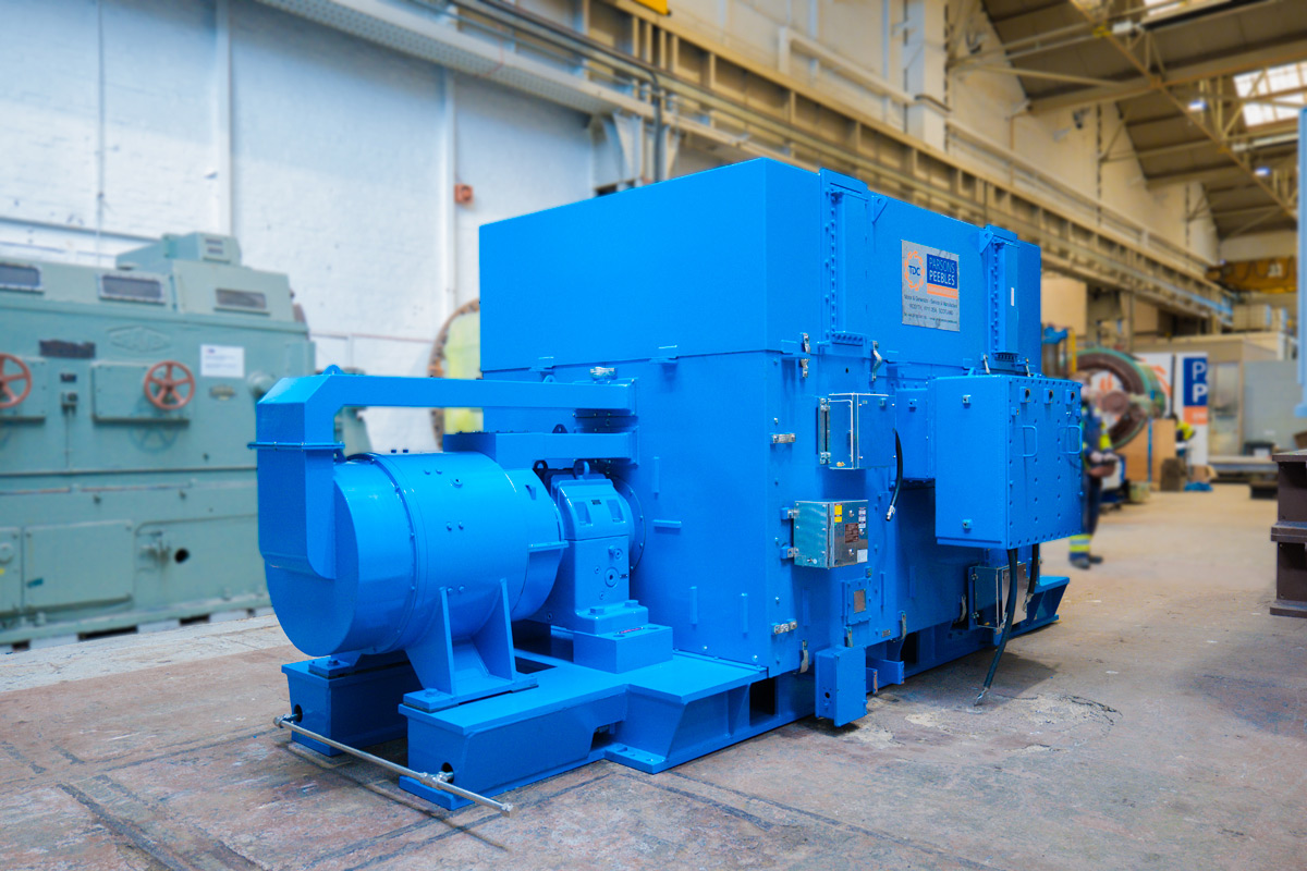
TDC Parsons Peebles designs, manufactures, and tests bespoke High Voltage Induction Generators tailored to severe industrial operating conditions. With an established engineering heritage dating back to 1896, our UK manufacturing facilities in Edinburgh and Birmingham produce tailored electrical machinery built strictly to IEC 60034, NEMA MG1, IEEE 841, and ISO 9001 quality standards.
Whether your installation requires an open drip-proof frame, a totally enclosed air-to-air cooled (CACA / IC611) structure, or a totally enclosed air-to-water cooled (CACW / IC81W) heat exchanger configuration, our engineering team custom-configures every unit for optimal thermal efficiency and mechanical rigidity.
Heavy-Duty Industrial HVIG (CACA / IC611)
Engineered for continuous power recovery in steel mills, chemical processing plants, and paper manufacturing facilities. Rated up to 13.8kV with robust Class H Vacuum Pressure Impregnation (VPI) insulation system.
Get Catalog
Renewable Hydro & Geothermal HV Generator
Custom-built for small-to-medium hydro schemes and geothermal energy installations. Features high overspeed withstand capabilities (up to 250% rated speed) and specialized thrust bearing assemblies for vertical or horizontal mounting.
Get Catalog
Hazardous Area ATEX / IECEx HV Generator (Ex ec / Ex p)
Certified by SGS Baseefa for Zone 1 and Zone 2 explosive atmospheres. Designed for offshore oil & gas platforms, refineries, and chemical storage networks requiring pressurization or non-sparking protection.
Get Catalog
Technical Specification Summary Grid
Below are the standard technical boundaries for TDC Parsons Peebles high-voltage induction generator product lines:
| Specification Attribute |
Standard Range / Technical Configuration |
| Power Output Capacity |
500 kW to 30,000 kW (30 MW+) |
| Rated Operating Voltages |
3,300V, 6,600V, 10,000V, 11,000V, 13,800V (custom windings available) |
| Frequency & Speed |
50 Hz (1500 / 1000 / 750 RPM) or 60 Hz (1800 / 1200 / 900 RPM); 2 to 16 poles |
| Enclosure Protection Types |
IP55, IP56, IP65; IC611 (CACA), IC81W (CACW), IC01 (Open Drip Proof) |
| Insulation System |
Class H micaceous insulation system impregnated with high-grade epoxy resin via automated Vacuum Pressure Impregnation (VPI), limited to Class B temperature rise ($80^\circ C$). |
| Hazardous Area Compliance |
ATEX / IECEx certified Ex ec (non-sparking), Ex p (pressurized), Ex eb (increased safety). Approved by SGS Baseefa. |
| Bearing Configurations |
Heavy-duty anti-friction rolling bearings or self-lubricating sleeve bearings with forced-oil lubrication systems and hydrostatic jacking oil lifts for low-speed startup. |
Strategic Procurement Guidance
3. Future Sourcing & Procurement Trends for High Voltage Induction Generators (2026–2035)
As global power infrastructure accelerates toward decarbonization, microgrid decentralization, and energy recovery optimization, procurement leaders, EPC directors, and asset managers are shifting how heavy electrical machinery is evaluated and purchased. Sourcing a high voltage induction generator is no longer a simple capital expenditure decision; it requires strategic risk management, supply chain resilience, and lifecycle total cost of ownership (TCO) evaluation.
Trend 1: The Dominance of "Drop-In Replacement" Engineering over Civil Modifications
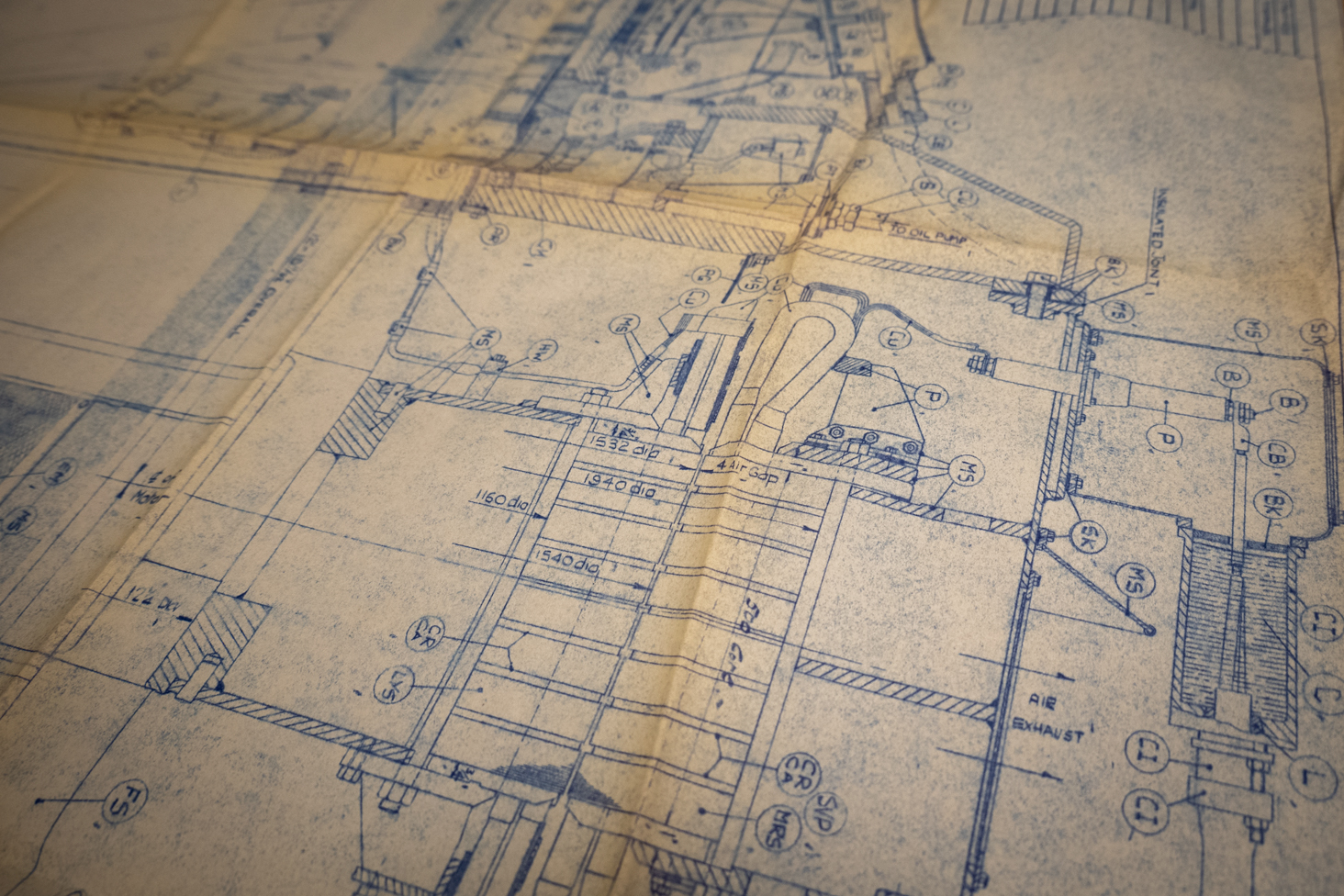
In mature industrial markets across Europe, North America, and East Asia, over 65% of high-voltage generator purchases involve replacing legacy machinery installed between 1970 and 2000 (such as legacy Peebles Electric, Bruce Peebles, Parsons Peebles, or GEC machines). Modern greenfield generators from generic manufacturers rarely match historical shaft center heights, foot hole dimensions, terminal box locations, or pipework interface coordinates.
Procurement Insight: Sourcing a custom-engineered "drop-in replacement" generator—which replicates 100% of the mechanical, electrical, and thermal interface footprint of the legacy machine—eliminates civil engineering redesigns, concrete foundation re-coring, and pipe rerouting. This saves plant operators hundreds of thousands of dollars in downtime and commissioning costs.
Trend 2: Rigorous Evaluation of Total Cost of Ownership (TCO) & Stator Efficiency
With escalating industrial electricity prices and carbon tax mechanisms, a 0.5% gain in high-voltage generator efficiency equates to tens of thousands of dollars in additional energy revenue annually over a 25-year operational lifespan.
Procurement evaluations are prioritizing low-loss electrical steel laminations (high-permeability silicon steel), optimized rotor bar geometries that minimize skin-effect stray load losses, and ultra-low friction bearing designs.
Trend 3: Mandatory Digital Twin Integration & Online Condition Monitoring
Modern high-voltage generator contracts now require integrated smart sensor suites embedded directly into the machine during factory assembly. Essential monitoring components include:
- Duplex Platinum RTDs (Pt100): Embedded in stator slot windings and bearing housings for real-time thermal modeling.
- Partial Discharge (PD) Couplers: Permanently installed high-voltage capacitive couplers to monitor insulation degradation without taking the unit offline.
- Tri-Axial Accelerometers: Continuous vibration spectrum analysis monitoring mechanical unbalance, shaft misalignment, or bearing raceway distress.
Industry Evolution & Future Outlook
4. Future Technological & Industry Development Trends in HV Induction Generators
The engineering landscape surrounding High Voltage Induction Generators is undergoing rapid evolution to support complex grid codes, renewable integration, and harsh environment operations:
1. Advanced Materials & High-Thermal VPI Resins
Next-generation high-voltage insulation systems employ nanostructured mica tapes and solventless epoxy resins engineered for extreme dielectric strength. These formulations increase thermal conductivity, withstand severe voltage harmonics ($THD$) caused by nearby frequency converters, and resist partial discharge erosion under prolonged thermal stress.
2. Duplex Copper-Alloy Rotor Bar Engineering
To combine low starting current inrush with maximum running efficiency, manufacturers are utilizing advanced rotor bar metallurgical structures. By combining high-conductivity copper bars with specialized bronze alloys or custom-extruded rotor slot profiles, induction generators can handle severe thermal expansion cycles during grid fault rides ($FRT$) without risking rotor bar cracking at the short-circuit end rings.
3. Integration with STATCOMs & Hybrid Microgrids
Historically, the main limitation of induction generators was their demand for reactive power ($kVAr$) from the grid. In modern industrial microgrids, high-voltage induction generators are paired with Static Synchronous Compensators (STATCOMs) or active front-end inverter systems. This hybrid architecture delivers the extreme mechanical ruggedness of an induction machine while providing sub-cycle dynamic reactive voltage control to satisfy stringent modern Grid Code compliance.
Manufacturing Heritage & E-E-A-T Authority
5. Why Leading Global Enterprises Partner with TDC Parsons Peebles
When specifying critical rotating electrical plant, global buyers demand proven experience, technical expertise, authoritative engineering certifications, and uncompromised reliability (E-E-A-T). TDC Parsons Peebles stands as a premier UK manufacturer and global service specialist, carrying forward an unbroken 128+ year legacy of electrical machine engineering excellence.
Engineering Track Record & Infrastructure
- 128+ Years of Manufacturing Excellence: Founded in 1896, our heritage includes iconic engineering institutions such as Bruce Peebles, Parsons Peebles, and Electric Products (Cleveland, Ohio).
- 12,141+ Machines Manufactured: Built in our UK facilities in Edinburgh and Birmingham, operating in the world's most demanding environments—from North Sea offshore platforms to Middle Eastern petrochemical complexes and African hydro sites.
- 200+ MVA Rotary Frequency Converter Installation Base: Demonstrating unmatched capability in high-voltage power conversion and custom electromagnetic design.
- World-Class Workshop & Rosyth Dockyard Location: Headquartered at Wood Road, Rosyth Royal Dockyard, Dunfermline, Fife, equipped with heavy crane lifting capacity (up to 100 tonnes), vacuum pressure impregnation tanks, dynamic balancing rigs, and state-of-the-art winding bays.
State-of-the-Art High Voltage Testing Capabilities
Every high voltage induction generator undergoes comprehensive testing prior to dispatch to verify compliance with contractual guarantees:
- Full No-Load HV Testing: Up to 13.8kV line voltage to verify magnetic flux distribution, core losses, phase balance, and mechanical balance.
- Back-to-Back Full Load Testing: Allowing high-voltage machines to be loaded to 100% capacity under full thermal stabilization conditions inside our UK test bay.
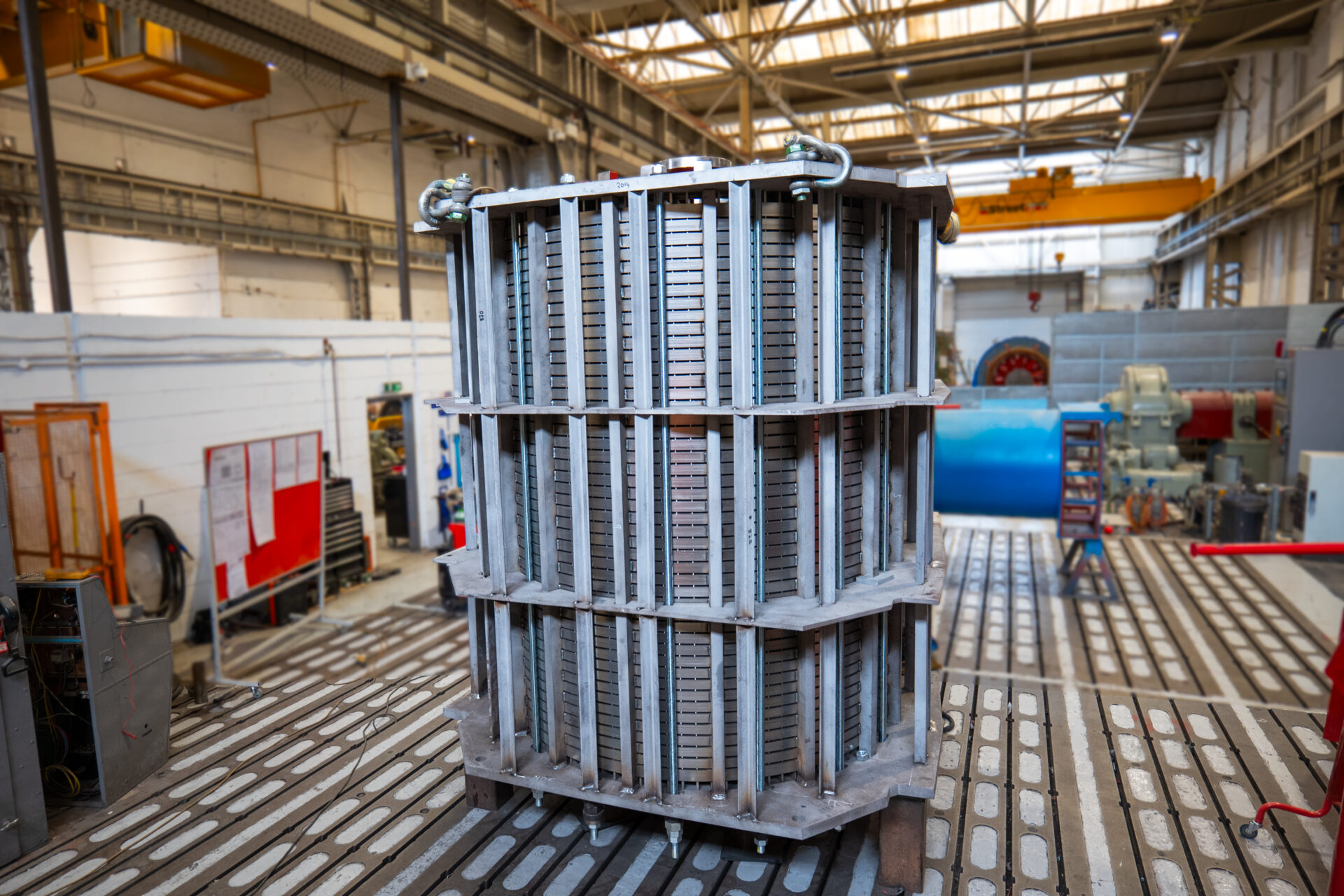
- Core Flux Testing: Utilizing high-frequency electromagnetic sensors to detect interlaminar insulation breakdown in stator core laminations before winding installation.
- High-Potential & Surge Testing: Dielectric validation in full compliance with IEC 60034-15 standards.
Globally Recognized Quality & Safety Accreditations
Proven Field Execution
6. Real-World Engineering Case Studies & Success Stories
Supporting Legacy Machines with Modern Engineering
TDC Parsons Peebles engineered a drop-in replacement high-voltage induction generator for a major refinery, preserving original foundation soleplates and restoring continuous power export with zero site downtime.
Read Case Study ›
Legacy Generator Reborn Through Precision Engineering
Complete overhaul, core re-lamination, and Class H VPI rewind of an 11kV high-voltage generator. The machine achieved a 4.2% power output upgrade while reducing bearing operating temperatures by $12^\circ C$.
Read Case Study ›
Transforming a 46-Year-Old Induction Generator
Extending the service life of an essential 6.6kV industrial waste-heat energy recovery induction generator. Modernized with digital online partial discharge sensors and Ex ec hazardous area compliance.
Read Case Study ›