





1. Strategic Imperative of High Voltage Motor Testing in Heavy Industry
In global industrial infrastructure—encompassing offshore oil & gas platforms, nuclear and thermal power generation plants, municipal water treatment facilities, chemical refining complexes, and heavy mining operations—High Voltage (HV) Electric Motors (operating typically between 3.3 kV and 13.8 kV+) serve as the primary electromechanical drivers for critical pumps, compressors, blowers, and mills. Unplanned catastrophic failure of an HV motor results not merely in localized machine repair costs, but in compounding downstream production outages running into hundreds of thousands of dollars per hour.
Consequently, global procurement executives, asset integrity directors, and senior electrical engineers require rigorous, standardized High Voltage Motor Testing regimes during factory acceptance testing (FAT), scheduled turnaround maintenance, and pre-commissioning phases. Modern testing goes far beyond rudimentary insulation resistance checks; it demands an integrated diagnostic methodology that interrogates the dielectric health of ground-wall insulation, inter-turn stress distribution, core-lamination integrity, thermal dispersion, and dynamic mechanical stability under rated load conditions.
Information Gain Key Takeaway for Procurement Teams:
Specifying factory-witnessed High Voltage Motor Testing compliant with IEEE 43, IEEE 95, and IEC 60034 standards provides verifiable proof of insulation longevity, eliminates infant mortality failures, and ensures 100% electrical and mechanical interchangeability for drop-in field replacement.
2. Comprehensive High Voltage Motor Testing Methodologies
Electrical degradation in high voltage rotating machines typically originates from thermal overstressing, voltage surges, partial discharge erosion, mechanical vibration, and environmental contamination. At TDC Parsons Peebles, our UK manufacturing and repair centers in Rosyth and Birmingham employ state-of-the-art diagnostic protocols designed to evaluate every critical parameter of high voltage induction and synchronous machines.
2.1 Insulation Resistance (IR) & Polarization Index (PI) Testing (IEEE 43-2013)
Insulation Resistance testing measures the DC resistance offered by the stator winding insulation to ground. The application of a continuous direct voltage (typically 2.5 kV to 10 kV DC depending on rated line-to-line voltage) induces charging currents across the dielectric barrier:
- Capacitive Charging Current: Rapidly decays to zero within seconds as the insulation charges.
- Polarization (Absorption) Current: Decays gradually over several minutes as dipole molecules in the resin matrix align with the electrical field.
- Conduction / Leakage Current: Remains constant across the insulation surface and through micro-fissures.
The Polarization Index (PI), defined as the ratio of the 10-minute insulation resistance to the 1-minute insulation resistance ($PI = R_{10min} / R_{1min}$), isolates moisture ingress, chemical contamination, and thermal cracking. Modern VPI (Vacuum Pressure Impregnation) Class F insulation systems manufactured by TDC Parsons Peebles consistently achieve PI values exceeding 3.0, far surpassing the IEEE 43 minimum requirement of 2.0.
2.2 Dissipation Factor (Tan $\delta$) & Capacitance Tip-Up Analysis (IEC 60034-27-3)
Dissipation Factor testing, commonly referred to as Tan Delta ($\tan \delta$) testing, is the gold standard for measuring global insulation degradation in high voltage stator coils. As insulation ages under thermal and dielectric stress, microscopic voids develop within the resin-mica matrix. When subjected to increasing AC voltage stress ($0.2 U_N$ up to $1.0 U_N$), partial discharges inside these voids cause a sharp increase in dielectric losses.
The Capacitance Tip-Up ($\Delta \tan \delta = \tan \delta_{1.0U_N} - \tan \delta_{0.2U_N}$) directly quantifies the volume of internal void fraction. TDC Parsons Peebles applies rigorous Tan Delta testing during coil fabrication, ensuring that every individual coil and completed stator block meets ultra-low tip-up thresholds, thereby guaranteeing maximum insulation density and thermal dissipation.
2.3 Partial Discharge (PD) Offline & Online Measurement (IEC 60034-27-1 / IEEE 1434)
Partial Discharge is a localized electrical breakdown that does not completely bridge the space between two conducting electrodes. In high voltage motors operating at $\ge 6.6\text{ kV}$, PD activity is both a primary symptom and an active agent of insulation failure.
Our test facilities utilize high-frequency capacitive couplers and ultra-wideband digital PD analyzers to capture pulse distributions in picocoulombs (pC). By analyzing Phase-Resolved Partial Discharge (PRPD) patterns, our engineers differentiate between:
- Internal Void Discharge: Symmetrical positive and negative pulse pattern, indicating manufacturing micro-voids.
- Slot Discharge: Asymmetrical pulses resulting from degradation of the conductive outer slot paint and coil movement within the core slot.
- End-Winding Corona Discharge: Surface discharge occurring at the exit of the stator slot due to contamination or insufficient stress control tape grading.
2.4 Stator Core Integrity: High/Low Flux Core Testing & El-CID
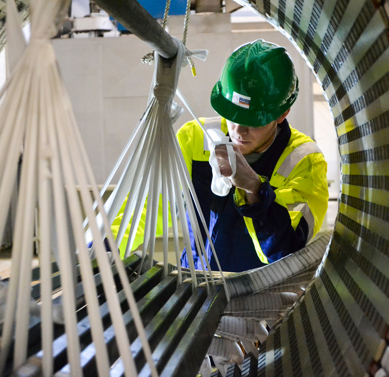
Inter-laminar insulation breakdown between adjacent silicon steel stator laminations creates localized circulating eddy currents. Left unchecked, these hot spots can melt the lamination steel, causing catastrophic stator fires. TDC Parsons Peebles performs both traditional High-Flux Ring Tests ($1.0\text{ to }1.5\text{ Tesla}$ thermal imaging) and Electromagnetic Core Imperfection Detection (El-CID) at low flux excitation ($4\%\text{ rated flux}$) to pinpoint lamination defects prior to or following stator rewinding.
Technical Comparison of Primary HV Motor Diagnostic Tests
| Diagnostic Test | Governing Standard | Primary Parameter Measured | Fault Detection Capability |
|---|---|---|---|
| Insulation Resistance & PI | IEEE 43-2013 / IEC 60034-27-1 | DC Leakage & Polarization Ratio | Moisture, surface contamination, gross insulation weakness |
| Tan Delta ($\tan \delta$) & Tip-Up | IEC 60034-27-3 / IEEE 286 | Dielectric Power Factor Change | Global insulation degradation, internal resin void content |
| Partial Discharge (PD) | IEC 60034-27-1 / IEEE 1434 | High-Frequency Charge Pulses (pC) | Localized void erosion, slot looseness, surface tracking |
| HV AC/DC Hi-Pot | IEEE 95 / IEC 60034-1 | Dielectric Withstand Capability | Critical ground-wall insulation punch-through validation |
| El-CID / Core Flux | IEEE 56 / EASA AR100 | Inter-laminar Eddy Current Leakage | Core hot spots, lamination short circuits, mechanical damage |
| Vibration & Modal Test | ISO 10816-7 / API 541 | Vibration Velocity (mm/s), FFT Spectrum | Unbalance, misalignment, bearing fault, structural resonance |
3. High Voltage Rotating Equipment Solutions Certified by TDC Parsons Peebles
Every high voltage machine manufactured or rewound in our UK workshops undergoes complete factory acceptance testing to ensure total compliance with operational environments—including hazardous areas requiring ATEX, Ex p, Ex ec, or Ex e certification. Below are our core product lines engineered specifically for high reliability and drop-in replacement capability.
Custom OEM Manufacturing
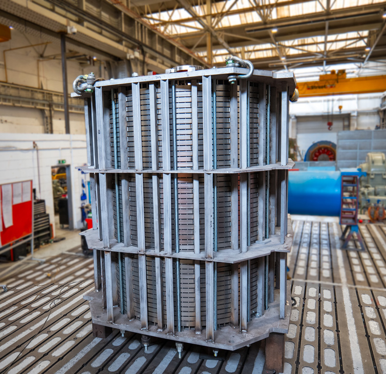
High Voltage Induction & Synchronous Motors
- Voltage & Power Range: 3.3 kV to 13.8 kV, output ratings up to 25 MW
- Enclosure & Cooling: TEFC (IC411), CACA (IC611), CACW (IC81W), NEMA I & II open drip-proof
- Hazardous Area Certifications: ATEX & IECEx certified for Ex ec, Ex p (pressurised), Ex e, and Ex d
- Drop-In Engineering: 100% duplicate mechanical footprint to retro-fit legacy Peebles, Bruce Peebles, Parsons, English Electric, AEI, GEC, and competitor machines
- Testing Assurance: Full load, direct load, back-to-back load testing, and severe ambient thermal run tests
Heavy Electrical Power
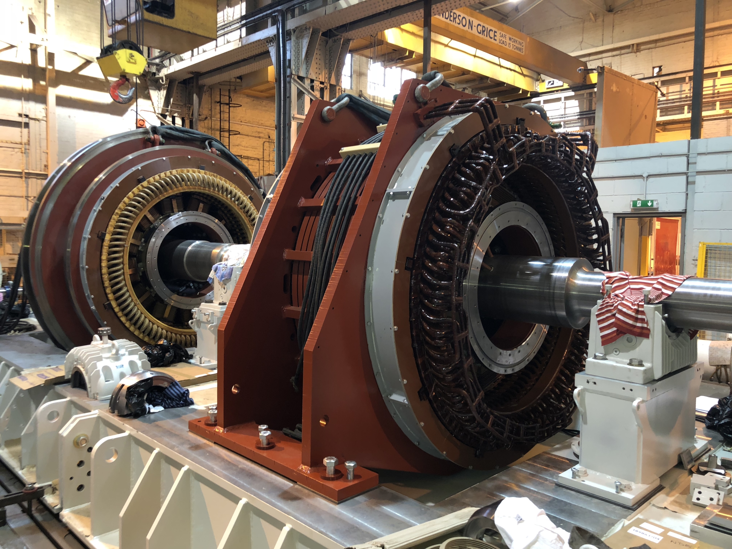
Industrial High Voltage Generators & Synchronous Condensers
- Generator Types: High Voltage Induction Generators, Slipring Generators, Salient Pole Synchronous Generators
- Applications: Hydro turbines, diesel engine drives, gas turbines, steam turbines, and grid frequency stabilization
- Custom Winding Design: High-dielectric Class H VPI insulation, thermal withstand for severe duty cycles
- Testing Verification: Over-speed spin testing, core flux validation, transient response analysis, and short-circuit withstand checks
Specialist Power Systems
Rotary Frequency Converters (RFC)
- Capacity Range: Individual units from 300 kVA to 20 MVA; total global installed base over 200 MVA
- Starting Current Optimization: Industry-leading low starting current (as low as $1 \times \text{FLC}$), minimizing weak grid disturbance
- Military & Industrial Shore Power: 50Hz to 60Hz or 400Hz conversion for naval dockyards and aviation testing facilities
- Full System Acceptance: Integrated dynamic full load testing with control switchgear prior to site delivery
4. Global Procurement Trends in High Voltage Motor Testing & Asset Management
As global industrial operators transition toward Industry 4.0 and strive for zero unplanned operational downtime, B2B procurement strategies for high voltage motors and diagnostic services are undergoing fundamental shifts:
- Mandatory Online Condition Monitoring & Digital Twin Integration: Global buyers increasingly demand that new HV motors come equipped with embedded fiber-optic RTDs, tri-axial vibration accelerometers, and permanent capacitive PD couplers. This sensor data feeds into cloud-based predictive analytics platforms to calculate real-time insulation Health Index numbers.
- Shift from Factory Standard Testing to Full-Load Synthetic & Back-to-Back Witnessing: Simple no-load testing at factory voltage is no longer sufficient for mission-critical installations. Procurement contracts now frequently mandate full temperature rise testing under actual thermal load using back-to-back configuration methods to verify cooling efficiencies and bearing dynamic stability prior to shipping.
- Prioritization of "Drop-In Replacement" Over Modifications: Civil engineering works and piping retrofits during brownfield plant revamps are prohibitively expensive. Procurement managers actively seek manufacturers capable of reverse-engineering legacy motor footprints—guaranteeing 100% duplicate shaft height, foot hole locations, terminal box orientations, and cooler connections.
- Rigorous ESG and Decarbonization Requirements: Total Cost of Ownership (TCO) analysis now dominates procurement evaluations. High voltage motors specified with premium efficiency levels (IE3/IE4 equivalent) and low electrical loss laminations reduce continuous operational carbon emissions significantly over a 30-year operational lifecycle.
5. Technological & Technological Trends in High Voltage Motor Testing
The field of high voltage electrical testing is rapidly advancing beyond periodic offline overhaul inspections into continuous, high-definition diagnostic frameworks. Modern developments shaping the sector include:
- Very Low Frequency (VLF) & Damped AC (DAC) Voltage Diagnostics: VLF testing allows field engineers to perform high-potential withstand testing at 0.1 Hz using significantly smaller, portable test sets while maintaining equivalent dielectric field stress across long stator cable connections and heavy windings.
- High-Resolution Phase-Resolved Partial Discharge (PRPD) Artificial Intelligence Filtering: Advanced signal processing algorithm isolates electrical noise generated by Variable Frequency Drives (VFDs) and plant switchgear, enabling noise-free online PD detection even in harsh industrial environments.
- Automated Thermographic Sweep & Core Flux Spectral Analysis: Combining digital infrared thermal imaging with high-frequency El-CID electromagnetic scanning allows instantaneous identification of microscopic inter-laminar shorts down to depth levels previously unreachable without core unstacking.
6. Why TDC Parsons Peebles is the Global Authority in HV Motor Testing & Manufacturing
Building on an unbroken engineering heritage dating back to 1896 (128+ years of technical leadership), TDC Parsons Peebles represents the pinnacle of UK electromechanical design, testing, and field support. Our facilities are built around a uncompromising commitment to Google E-E-A-T principles (Experience, Expertise, Authoritativeness, and Trustworthiness).
Proven Manufacturing Track Record
Over 12,141+ electrical machines custom-manufactured in Edinburgh, Rosyth, and Birmingham, UK, alongside over 1,165 heavy machines produced by our legacy Electric Products division in Cleveland, Ohio.
Hazardous Area Certification Authority
Full ATEX and IECEx certification capability through SGS Baseefa for Ex ec, Ex p, Ex e, and Ex d hazardous environments, assuring absolute safety in explosive oil & gas atmospheres.
100% Drop-In Replacement Capability
Unrivaled archive of historical engineering drawings allowing us to manufacture 100% interchangeable drop-in replacement motors for legacy Bruce Peebles, Parsons, GEC, and competitor units.
Real-World Case Studies: Precision Testing & Overhaul
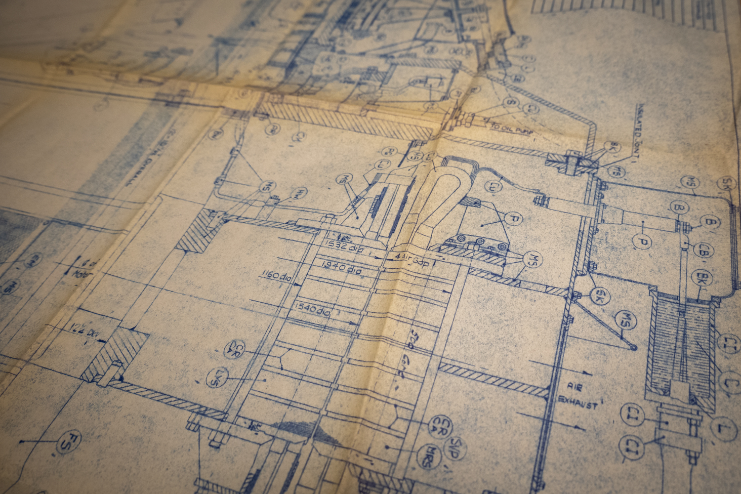
Legacy Machine Modernization
Complete stator core flux validation, VPI rewind, and high-voltage dielectric testing to extend operational life by 30+ years.
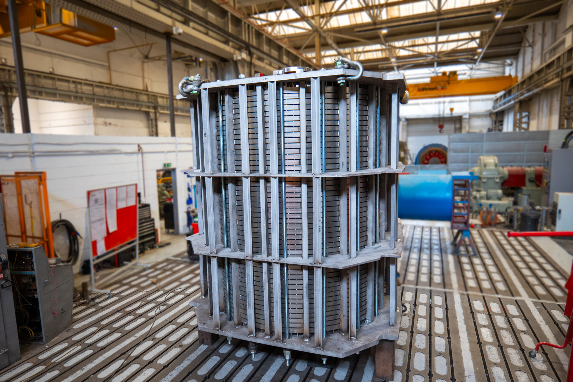
Legacy Generator Reborn
Full mechanical overhaul, dynamic balancing, Tan Delta verification, and full-load back-to-back testing for offshore energy asset.
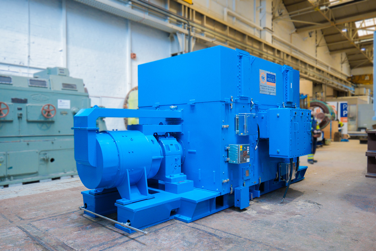
46-Year-Old Generator Overhaul
Complete structural rebuild and full-spectrum electrical testing, converting a legacy unit into a high-efficiency powerhouse.
Frequently Asked Questions (FAQ)
Key Engineering & Procurement Inquiries Addressed by Industry Experts
Q1: What are the governing international standards for High Voltage Motor Testing?
High voltage motor testing relies on several key global standards: IEEE 43-2013 (Insulation Resistance & Polarization Index testing), IEEE 95 (DC Dielectric Withstand testing), IEC 60034-27-1 (Offline Partial Discharge measurement), IEC 60034-27-3 (Dielectric Dissipation Factor / Tan Delta testing), and API 541 / API 547 (Special purpose induction motors for petroleum and chemical industries). Factory witness testing at TDC Parsons Peebles strictly aligns with these standards.
Q2: Why is Dissipation Factor (Tan $\delta$) Tip-Up testing mandatory for high voltage stators?
Tan Delta ($\tan \delta$) Tip-Up testing measures the increase in electrical losses as voltage rises from $0.2 U_N$ to $1.0 U_N$. An elevated tip-up value indicates the onset of partial discharges within micro-voids in the resin-mica ground-wall insulation. Performing this test ensures that the Vacuum Pressure Impregnation (VPI) process has achieved 100% resin penetration without air pockets.
Q3: What is the difference between Direct Load Testing and Back-to-Back Load Testing?
Direct Load testing connects the motor under test to a mechanical load absorbing dynamometer. However, for super-large megawatt high voltage motors, direct loading requires immense electrical power grid capacity. Back-to-Back Load Testing pairs two identical machines (one motor, one generator) mechanically coupled and electrically interconnected. This method allows full rated thermal current and voltage stress to be achieved while drawing only system loss power from the utility grid.
Q4: How does Partial Discharge (PD) testing protect Ex p (Pressurised) hazardous area motors?
Ex p motors operate in potentially explosive gas atmospheres (such as Zone 1 or Zone 2). Internal partial discharge can create high-temperature arcs or localized hot spots capable of igniting surrounding flammable mixtures if pressurization fails or during start-up. Pre-commissioning offline and online PD testing ensures the stator insulation is completely free of high-energy discharge sites, satisfying ATEX/IECEx safety audits.
Q5: How does Electromagnetic Core Imperfection Detection (El-CID) compare to traditional High-Flux testing?
Traditional High-Flux testing requires magnetizing the stator core to rated flux density ($1.0\text{ to }1.5\text{ Tesla}$), which demands heavy high-voltage supply cables and carries the risk of thermal damage if severe hot spots exist. El-CID operates at only $4\%$ of rated excitation flux, utilizing a sensitive Pick-Up Coil to detect magnetic flux leakage caused by inter-laminar fault currents. El-CID is safer, faster to set up, and exceptionally precise for localized core repairs.
Q6: Can TDC Parsons Peebles build a drop-in replacement motor for non-Parsons OEMs?
Yes. TDC Parsons Peebles possesses vast archival drawing records and advanced 3D laser scanning capabilities. We regularly engineer and manufacture 100% drop-in replacement motors matching exact center heights, shaft extensions, mounting foot hole centers, and terminal box coordinates for legacy machines originally supplied by GEC, AEI, English Electric, Siemens, ABB, and Bruce Peebles.
Q7: What documentation and test certificates are provided following Factory Acceptance Testing (FAT)?
Every machine tested in our UK facility receives a complete ISO 9001-certified FAT Dossier. This includes raw data and calibrated curves for Insulation Resistance/PI, Winding Resistance, High-Voltage AC/DC Hi-Pot, Tan Delta & Tip-Up, Phase-Resolved Partial Discharge, No-Load Characteristic Curves, Shaft Voltage, Dynamic Vibration Spectrum, and Sound Pressure Level measurements.
Q8: How often should high voltage motor diagnostic testing be performed during plant operation?
For critical HV assets, offline baseline testing (IR, PI, Tan Delta, PD) should be conducted during plant turnaround shutdowns every 3 to 5 years. Online Partial Discharge and continuous vibration monitoring should be conducted permanently or quarterly to detect early insulation breakdown or mechanical degradation prior to scheduled maintenance windows.
Request High Voltage Motor Technical Specifications & Testing Services
Partner with TDC Parsons Peebles for engineering expertise backed by 128+ years of UK manufacturing heritage. Access detailed product catalogs, test bay capabilities, and custom OEM replacement engineering.