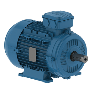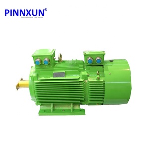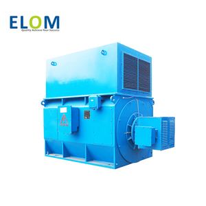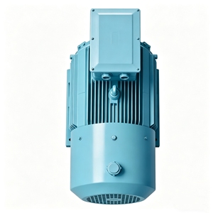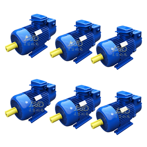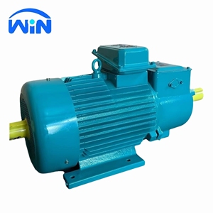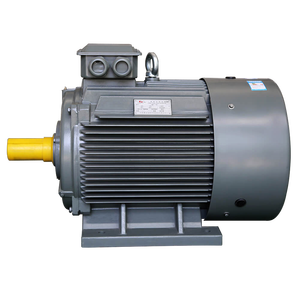





Explore our engineered lineup of CE-marked medium voltage motor drives, high-torque wound rotor induction systems, and heavy-duty AC rotating machinery built for extreme industrial operational demands.
Medium Voltage Drives (MVDs)—typically operating in the power frequency range from 2.3 kV up to 13.8 kV—serve as the critical backbone for energy-intensive global industries including power generation, oil and gas processing, mining extraction, municipal water utilities, and heavy metallurgical manufacturing. Unlike Low Voltage (LV) drives which rely on simple two-level pulse-width modulation (PWM), industrial MV drives demand sophisticated multi-level semiconductor topologies to deliver near-sinusoidal voltage waveforms, prevent insulation breakdown, and adhere strictly to international Electromagnetic Compatibility (EMC) regulations mandated under European CE marking directives.
To comply with CE Directives (Low Voltage Directive 2014/35/EU and EMC Directive 2014/30/EU) alongside rigorous international standards like IEC/EN 61800-3 and IEC/EN 61800-5-1, premium MV drive manufacturers implement advanced multi-level power conversion architectures. The primary architectural approaches adopted by world-class manufacturers include:
| MV Drive Topology | Typical Voltage Rating | Harmonic Distortion (THD) | dv/dt Stress on Motors | Primary Industrial Applications |
|---|---|---|---|---|
| Cascaded H-Bridge (CHB) | 3.3 kV to 11 kV | Very Low (< 2-3% without filters) | Negligible (Multi-step waveform) | Pumps, Centrifugal Fans, Compressors, Power Plant Draft Fans |
| Neutral Point Clamped (NPC) / 3-Level | 2.3 kV to 4.16 kV | Moderate (Requires phase-shift trans) | Moderate (Filters required for long leads) | Rolling Mills, Marine Propulsion, High-Power Extruders |
| Modular Multilevel Converter (MMC) | 6.6 kV to 13.8 kV+ | Ultra-Low (< 1.5%) | Minimal (Smooth sinusoidal step) | Flexible AC Transmission Systems (FACTS), Heavy Industry Grids |
| Current Source Inverter (CSI) | 2.4 kV to 6.6 kV | Low on Input, Sinusoidal Output | Low (Integrates output capacitor) | Large Kiln Drives, Mine Hoists, Constant Torque Loads |
Harmonic distortion injected back into the utility grid represents one of the major engineering hurdles in medium voltage power conversion. Modern CE certified MV drive suppliers mitigate line-side harmonics using phase-shifting isolation transformers configured in multi-pulse arrangements (such as 18-pulse, 24-pulse, 36-pulse, or 54-pulse secondary windings). This phase-cancellation technique eliminates key lower-order harmonics (5th, 7th, 11th, and 13th), easily satisfying the strict harmonic current voltage limits specified in IEEE 519-2022 guidelines without requiring complex external harmonic filters.
Furthermore, for applications requiring regenerative braking—such as downhill overland conveyors, mine hoists, and high-inertia centrifuge systems—leading MV drive suppliers offer Active Front End (AFE) topologies using IGBT rectification. AFE drives allow bi-directional power flow, returning braking energy clean to the main power grid while maintaining a unit power factor (cos φ ≈ 0.99) across the entire operating speed range.
Discover how state-of-the-art power electronics, modular hardware design, and intelligent control algorithms redefine reliability and lower Total Cost of Ownership (TCO).
Cascaded multi-level topologies keep output voltage step changes (dv/dt) below 1000V/μs, guarding motor winding insulation against partial discharge and voltage spikes—eliminating the need for specialized inverter-duty transformers or long-cable filters.
Equipped with solid-state bypass mechanisms (N+1 or N+2 power cell redundancy). In the event of a power module semiconductor fault, the drive dynamically bypasses the failed cell within milliseconds, maintaining continuous industrial process operation.
Embedded high-speed FPGA microprocessors continuously analyze thermal profiles, DC-link capacitor health, switching frequency ripple, and output vibration spectra—providing cloud-connected predictive maintenance metrics long before failure occurs.
As global industrial sectors undergo systemic decarbonization and push toward Net-Zero carbon emissions, the procurement dynamics for medium voltage variable speed drives are shifting rapidly from capital cost focus (CapEx) to lifetime lifecycle efficiency and operational carbon footprint reduction (OpEx optimization). Procurement managers and principal engineering consultants must navigate several emerging technological vectors:
Silicon-based Insulated Gate Bipolar Transistors (IGBTs) have reached physical switching speed and thermal limits. Next-generation MV drive suppliers are incorporating Silicon Carbide (SiC) power modules into 3.3kV and 6.6kV drive stages. SiC semiconductors offer switching losses up to 70% lower than conventional silicon, enabling higher switching frequencies, drastically smaller passive filtering components, smaller footprint control cabinets, and overall system efficiency exceeding 99.1% at rated load.
Across Europe, North America, and East Asia, thousands of industrial facilities operate aging fixed-speed direct-on-line (DOL) high voltage motors installed decades ago. Retrofitting these legacy assets with variable speed control used to require extensive civil engineering work, replacement of motor cables, and custom structural foundations. Modern MV drive manufacturers now provide highly engineered, standardized "Drop-In Retrofit" MV Drive systems featuring integrated phase-shifting isolation transformers, compact liquid-to-air cooling options (CACA/CACW), and sine-wave output filters that allow existing standard induction or wound rotor motors to run reliably without insulation breakdown.
With the rapid penetration of intermittent renewable power into high-voltage transmission grids, industrial facilities are penalized for reactive power draw and voltage unbalance. Modern CE certified MV drive systems feature integrated Digital Twin software modules and microsecond-level grid synchronization. These smart drives function dynamically as static VAR compensators (STATCOMs) when running under partial loads, stabilizing plant power factor and supporting localized grid stability.
When evaluating global Medium Voltage Drive manufacturers and custom system integrators, proven engineering heritage, stringent quality assurance certifications, and comprehensive full-power load testing facilities form the tri-pillar foundation of reliability. Building upon a 128+ year legacy of electrical machinery innovation originating from world-class UK manufacturing bases in Rosyth, Dunfermline, and Birmingham, our technical engineering capabilities setting the industry benchmark include:
Addressing fundamental technical questions faced by procurement teams, plant managers, and electrical engineering consultants during drive evaluation.
CE certification for Medium Voltage Drives requires strict compliance with the Low Voltage Directive (2014/35/EU) applied via IEC/EN 61800-5-1 (safety requirements: electrical, thermal, and energy hazards) and the EMC Directive (2014/30/EU) under IEC/EN 61800-3. Certified manufacturers perform dielectric voltage withstand testing, impulse withstand tests, short-circuit withstand validation, thermal rise testing under full load, radiated and conducted emissions testing in shielded chambers, and immunity testing against high-voltage surges and fast transients.
In 6.6kV applications, a CHB drive utilizes multiple low-voltage single-phase power modules connected in series per phase (typically 5 to 6 cells per phase) powered by an multi-pulse isolation transformer. This creates a multi-step waveform with extremely low harmonic distortion (THD < 2%) and minimal dv/dt stress on the motor, making it ideal for standard motors over long cable distances. Conversely, a 3-Level NPC drive uses fewer high-voltage semiconductors operating at higher voltage steps, requiring a simpler transformer but necessitating output sine-wave filters to protect standard motor windings.
Yes, provided the MV drive selected utilizes a low dv/dt multi-level topology (such as a 17-level or 21-level Cascaded H-Bridge arrangement) or includes an integrated LC output sine-wave filter. These technologies smooth the output voltage pulse train into a pure sinusoidal wave, keeping peak voltage spikes ($V_{peak}$) within Class F/H insulation capabilities and preventing premature insulation breakdown caused by partial discharge.
For dusty or corrosive industrial environments (such as cement kilns, chemical plants, or ocean vessels), Air-to-Water heat exchanger cooling (CACW / Liquid Cooled) or sealed cabinet forced-air cooling with air-to-air heat exchangers (CACA) are recommended. Liquid-cooled MV drives offer a 50% smaller enclosure footprint, completely isolate power semiconductors from ambient dust/gases, and quiet operation below 70 dB(A).
TCO is calculated using the formula: TCO = CapEx + OpEx (Energy Consumption) + Maintenance - Salvage Value. Because centrifugal pumps and fans follow Affinity Laws (where power consumed is proportional to the cube of speed, $P \propto N^3$), reducing speed by just 20% drops energy consumption by nearly 50%. In typical 6kV 2000kW pumping applications, energy savings pay back the initial MV Drive investment within 12 to 18 months of continuous operation.
In N+1 redundant MV drive architectures, each power cell is fitted with a fast solid-state thyristor or contactor bypass circuit. When the internal diagnostic controller detects an IGBT failure or over-temperature condition in a specific cell, it triggers the bypass mechanism in under 10 milliseconds while simultaneously adjusting the phase angles of the remaining healthy cells via vector control software. The motor continues to run seamlessly at 100% torque without process interruption.
Connect directly with our senior power systems engineering team to request customized technical specifications, electrical CAD drawings, harmonic calculation studies, or custom product catalogs.
Get Catalog