




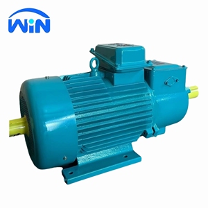
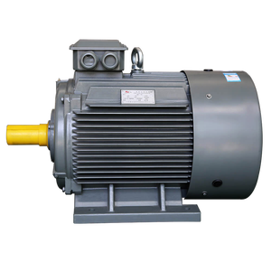
Technical Whitepaper: Engineering Architecture of Brushless Alternators & Heavy Industrial Induction Systems
In modern industrial utility grids, continuous manufacturing facilities, offshore energy platforms, and heavy marine vessels, electrical power stability depends directly on the electromagnetic integrity of the generation equipment. As premier OEM/ODM Brushless Alternator manufacturers and suppliers, our engineering paradigm centers on addressing critical energy conversion challenges: voltage dip mitigation, harmonic suppression, thermal endurance under transient overloads, and eliminating mechanical contact wear points.
Unlike traditional slip-ring or brushed alternator configurations that suffer from carbon dust contamination, brush bounce, and high maintenance overhead, modern brushless synchronous alternators utilize an integrated brushless exciter and rotating rectifier assembly. This technical whitepaper explores the electromagnetic design, insulation advancements, thermal fluid dynamics, and global sourcing paradigms governing current and future electrical rotating machines.
1. Electromagnetic Topologies: Brushless Excitation vs. Slip-Ring Winding Systems
The core operating principle of a brushless alternator rests upon a two-stage electromagnetic structure contained within a single mechanical enclosure: the main generator system and the exciter system. The main generator consists of a rotating field (rotor) and a stationary armature (stator). Conversely, the exciter system operates in reverse—with a stationary field winding and a rotating armature winding.
When the Automatic Voltage Regulator (AVR) delivers direct current (DC) to the stationary exciter stator field, it induces a three-phase alternating current (AC) in the rotating exciter rotor. This AC voltage is fed immediately into a shaft-mounted 3-phase full-wave bridge rectifier (comprising high-surge silicon diodes and surge-suppressing varistors). The rectified DC current flows directly into the main rotor field windings without requiring slip rings, carbon brushes, or commutator bars.
- Elimination of Arching & Carbon Dust: Eliminates electrical sparking in explosive atmospheres (essential for ATEX/IECEx hazardous zone applications). Carbon dust buildup—a primary root cause of insulation breakdown in slip-ring AC motors—is entirely avoided.
- Low Harmonic Distortion (THD): Engineered with 2/3 pitch stator windings to eliminate 3rd, 9th, and 15th triple harmonics. This configuration prevents neutral conductor overheating when powering non-linear IT, inverter, or UPS loads.
- Enhanced Transient Voltage Response: Utilizing Permanent Magnet Generators (PMG) as an independent pilot exciter ensures sustained short-circuit current capability (typically 300% rated current for 10 seconds), preventing voltage collapse during heavy inductive motor starting.
Data Visualization: Technical Comparison of Industrial Rotating Machines
To assist procurement managers, EPC contractors, and electrical design consultants in selecting optimal power conversion machinery, the following matrix compares standard industry parameters across motor and alternator series:
| Machine Series / Category | Voltage Range | Power Output / Rating | Excitation / Winding Type | Efficiency Rating | Typical Industrial Duty |
|---|---|---|---|---|---|
| Standard Brushless Alternators | 380V - 13.8 kV | 50 kVA - 20,000 kVA | Brushless AC Exciter + AVR / PMG | IE3 / IE4 Equivalent (94-97.5%) | Prime Power, Standby Gensets, Marine Auxiliaries |
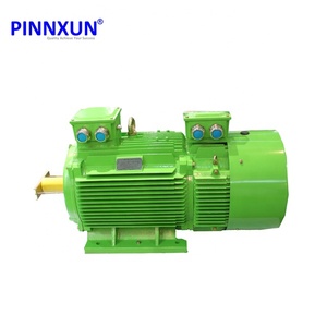
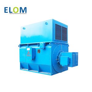
| YR / YZR Wound Rotor Motors | 380V - 10 kV | 5.5 kW - 3,200 kW | Heavy-Duty Slip Ring Winding | High Torque / Low Inrush Current | Bridge Cranes, Steel Rolling Mills, Mining Hoists |
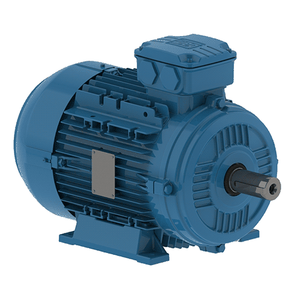
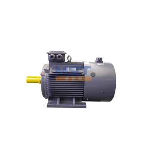
| YE2 / WEG Induction Series | 380V - 660 V | 0.75 kW - 315 kW | Squirrel Cage Asynchronous | IE2 Premium Energy Savings | Industrial Fans, Centrifugal Pumps, Compressors |
| Salient Pole Synchronous Generators | 3.3 kV - 15 kV | 1 MVA - 50 MVA | Brushless Static or Rotary Exciter | High Efficiency (Up to 98.2%) | Hydroelectric Plants, Steam/Gas Turbine Drive |
| Rotary Frequency Converters | 400V / 480 V (50/60/400Hz) | 300 kVA - 20 MVA | Dual Synchronous Motor-Generator set | Clean Sinusoidal Output | Defence Dockyards, Aviation Power, Shore-to-Ship |
2. Advanced Insulation Systems & Thermal Management Engineering
The lifespan of a high-voltage synchronous alternator or heavy wound-rotor induction motor is fundamentally determined by the dielectric strength and thermal tolerance of its winding insulation system. Modern industrial operating environments expose rotating machinery to corrosive salt spray, high humidity, conductive dust, and cyclic thermal expansion shocks.
Our custom OEM/ODM manufacturing processes incorporate Class H synthetic insulation systems resin-impregnated via Vacuum Pressure Impregnation (VPI). VPI removes micro-voids, air pockets, and moisture from deep within the stator slot coils, replacing them with solventless epoxy resin formulated to withstand mechanical stresses caused by rapid magnetic reversal forces.
- Thermal Class Superiority: Machines are engineered with Class H insulation materials (rated for 180°C maximum thermal limit) but operational temperature rises are restricted to Class B limits (80°C rise). This 70°C thermal safety margin extends insulation dielectric lifetime exponentially according to Arrhenius thermodynamic rate principles.
- Cooling Enclosure Options: Depending on environment severity, units are manufactured in TEFC (Totally Enclosed Fan Cooled - IP55), CACA (Totally Enclosed Air-to-Air Cooled - IC611), or CACW (Totally Enclosed Air-to-Water Cooled - IC81W) for quiet, ultra-compact indoor installations.
- Stator Slot Wedging & End-Winding Bracing: High-torque wound rotor series (such as the YR 3200kW series) incorporate glass-ribbon end-ring lacing and epoxy-glass slot wedges to absorb massive electrodynamic radial impact forces encountered during direct-on-line (DOL) switching or mechanical rotor lockups.