





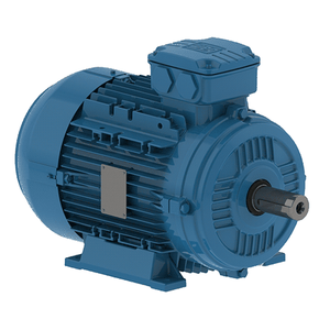
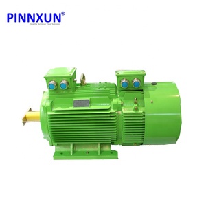
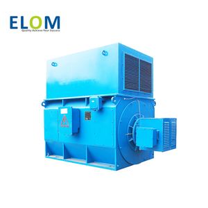
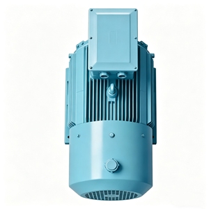
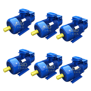
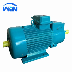
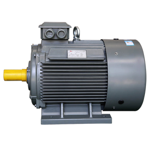
In modern high-capacity heavy industries, electric power conversion efficiency, grid stability, and operational reliability stand as the triple pillars of operational excellence. As power demands for industrial continuous-duty applications scale from megawatt-level gas compressors to heavy-duty mining crushers, selecting the optimal rotating machinery infrastructure becomes a paramount engineering decision. Brushless synchronous motors have emerged as the paramount choice for plant operators and EPC contractors seeking maximum operational efficiency, power factor correction, and explosive-environment safety compliance.
Unlike standard squirrel-cage induction machines or legacy slip-ring wound rotor induction motors (such as YR and YZR series motors), a brushless synchronous motor operates at exact synchronous speed determined by the grid frequency ($N_s = 120f/P$) completely independent of load variations. The critical engineering advantage lies in the complete elimination of sliding mechanical contacts—specifically carbon brushes, slip rings, and commutator assemblies. By integrating an internal rotating ac exciter and a shaft-mounted solid-state three-phase full-wave diode bridge rectifier, excitation power is magnetically coupled directly onto the rotor shaft.
The brushless excitation assembly operates as an inverted synchronous generator: the stationary stator field receives controlled direct current (DC) from an Automatic Voltage Regulator (AVR) or digital field controller, while the rotating armature generates three-phase AC power. This AC current is immediately rectified into DC on the main rotor via shaft-mounted silicon rectifiers shielded against severe centrifugal forces. This field DC feeds directly into the main salient-pole or cylindrical synchronous rotor poles, creating a rigid magnetic lock with the revolving stator MMF (magnetomotive force) wave.
| Technical Parameter | Brushless Synchronous Motor | Wound Rotor Induction (Slip-Ring) | Standard Asynchronous Induction |
|---|---|---|---|
| Speed Regulation | 0% (Exact Synchronous Speed) | 1% - 5% Slip Dependent | 2% - 5% Load Dependent |
| Power Factor Capability | Adjustable (0.8 Leading to 1.0 Unity) | Fixed Lagging (0.82 - 0.88) | Fixed Lagging (0.80 - 0.87) |
| Maintenance Cycle | Ultra-Long (50,000+ Hrs Bearings Only) | Frequent Brush & Ring Wear Replacement | Standard Bearing Maintenance |
| Hazardous Area Rating | Ideal for ATEX Ex p / Ex ec Zone 1 & 2 | Restricted due to Collector Ring Sparking | Standard Ex d / Ex ec Options |
| Starting Torque & Inrush | Low Inrush via Damper Winding / VFD | Very High Starting Torque / Low Inrush | High Inrush Current (5x - 7x FLC) |
As global manufacturing centers accelerate decarbonization targets, energy efficiency directives (such as EU MEPS, US DOE regulations, and China GB18613 standards) are mandating a transition toward premium efficiency (IE4) and super-premium efficiency (IE5) electric motor drives. Buyers and procurement managers must align their supply chain sourcing strategies with four dominant macro trends:
Trend 1: Total Cost of Ownership (TCO) Sourcing vs. Initial Capital Expenditure: Historical procurement models focused primarily on initial landed equipment cost. However, in continuous 24/7 operating environments (such as municipal water pumping, oil refining, and fertilizer manufacturing), electricity consumption accounts for over 92% of an electric motor's lifetime operational cost. Brushless synchronous machines offer operational efficiencies exceeding 97.5% in high-megawatt ratings, allowing global plants to amortize initial procurement price differentials within 14 to 22 months of continuous operation.
Trend 2: Seamless "Drop-In" Replacement Engineering: Aging industrial plants in North America and Western Europe installed heavy rotating machinery between 1970 and 1995. Replacing legacy machines with modern units often incurs exorbitant civil modification costs if foundation footings, shaft center heights, or terminal box locations differ. Leading OEM manufacturers now specialize in 100% mechanically and electrically interchangeable drop-in replacement designs, retaining original footprint geometry while integrating 21st-century VPI insulation and brushless digital field regulation systems.
Trend 3: Integration of IoT Smart Diagnostics & Condition Monitoring: Modern high-voltage motor procurement specifications now standardly demand embedded sensor arrays: PT100 RTDs for stator windings and bearings, tri-axial vibration accelerometers, and partial discharge (PD) monitoring couplers. Real-time telemetry data is fed into centralized SCADA and predictive maintenance algorithms to prevent catastrophic insulation breakdown or bearing failure.
Advanced Vacuum Pressure Impregnation (VPI) utilizing solventless epoxy resins ensures void-free dielectric integrity, superior thermal dissipation, and resistance to aggressive chemical environments.
Precision-engineered rotor damper windings (Amortisseur circuits) provide robust damping against grid frequency fluctuations and mechanical load surges, preserving synchronism under extreme load steps.
Fully certified Ex p (pressurized) and Ex ec (non-sparking) enclosures engineered to safely operate in combustible gas atmospheres across offshore platforms, chemical refineries, and grain handling facilities.
Versatile cooling configurations including CACA (Air-to-Air, IC611), CACW (Air-to-Water, IC81W), and open drip-proof screen protected enclosures matched specifically to site ambient conditions.
100% rigorous factory testing protocols including Full Load Back-to-Back testing, Core Flux inspection, Dielectric Withstand tests, and Dynamic Balancing to ISO 1940 Grade G1.0 standards.
Engineered cast iron and fabricated structural steel frames offering high mechanical stiffness, low acoustic emissions, and resonant-free natural frequency bands under variable speed operation.
Building upon a historic manufacturing legacy dating back to 1896, our UK-based production and testing facilities (spanning renowned engineering locations in Dunfermline, Rosyth Royal Dockyard, Edinburgh, and Birmingham) represent the pinnacle of high voltage electrical machine design. Having manufactured over 12,141 high-voltage machines and installed more than 200 MVA of rotary frequency converters globally, our engineering team delivers bespoke motor and generator solutions tailored to the world's most unforgiving operational environments.
Operating under ISO 9001, ISO 14001, and ISO 45001 standards with full hazardous area certifications approved by SGS Baseefa and AEMT membership.
Specialized capability to support legacy machines, providing exact drop-in replacements for obsolete OEMs without modifying site foundations or piping systems.
In-house high voltage testing bay capable of Direct Load, Back-to-Back load testing, No-Load characterization, and core flux loop testing up to full rated system voltages.
Field service engineers deployed worldwide for dynamic balancing, vibration analysis, emergency rewinds, site installation, and life-extension overhauls.